Suntan Monolithic/Multilayer Ceramic Capacitors

Suntan Technology Company Limited
----All Kinds of Capacitors

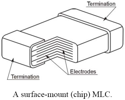
MLC capacitors are marvels of modern material science. Manufacturing MLC capacitors is considerably more complicated than manufacturing dipped ceramic capacitors. First, the base ceramic material is mixed with a binder and fashioned into thin sheets. Electrodes are painted onto one side of the sheets using a paint that consists of a liquid binder with fine metal particles in suspension. The metals that are used include gold, palladium, platinum, and silver alloys. The reason for using these metals is that when the base ceramic is fired, oxygen is required for the ceramic proper to form. If one uses a metal such as iron, for example, it would oxidize completely during the firing process.Precious metals do not have this problem, but is a major cost component of monolithic ceramic capacitors. However, recently some manufacturers have reported using nickel and copper for the electrodes. This promises to reduce the cost of the raw materials, but at the expense of more elaborate manufacturing processes.

Once the ink is dry, the sheets are stacked on top of each other. The painted electrodes are arranged so that alternate electrodes exit from opposite ends. The top and bottom most layers do not have painted electrodes. The laminated layers are then compressed and fired, which sinters them into one monolithic structure.

Next, the ends are terminated, often using silver. For leaded capacitors, wires are attached, and finally the capacitor is encapsulated in plastic and marked. In the case of chip capacitors, the silver end terminations are covered with tin to aid soldering. The whole capacitor may be covered with lacquer.

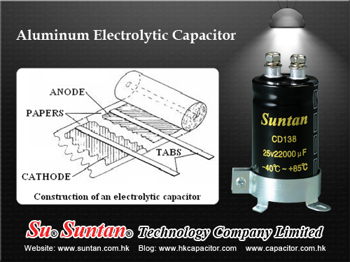
Construction Details of A Wet Aluminum Electrolytic Capacitor - Production Process

Suntan Technology Company Limited
---All Kinds of Capacitors

Aluminum electrolytic capacitors are comprised of anode and cathode plates separated by an absorbent spacer. As shown in Figure below, metal tabs are attached to the anode and cathode plates, and the assembly is wound into a cylindrical section. The tabs are welded to aluminum terminals installed in a header (top). The section-header assembly is immersed in a bath of hot capacitor electrolyte (significantly different from the formation process electrolyte). In what is called the impregnation process, a vacuum is applied to the electrolyte and sections, causing electrolyte to be drawn into the sections, thoroughly wetting the sections. The sections are placed in aluminum cans, and the headers are sealed to the cans. The capacitor units are slowly brought up to maximum rated voltage at maximum rated temperature during the aging process. The aging process grows oxide on areas on the anode foil which have an insufficient oxide barrier, such as slit edges and places which have been cracked during the winding operation. Inspections and tests occur at several stages of the production process.

For more details please check : http://www.capacitors.hk/Aluminum-Electrolytic-Capacitors/

How do Run Capacitors work?

A capacitor, also known as a condenser, is a component in electronic devices. It consists of a combination of three objects. First, a pair of objects called conductors conducts electricity. The conductors are separated by a dielectric, which is a substance that does not conduct electricity. Common dielectrics include substances such as paper, ceramic and plastic.

When an electric current exists between the two conductors, it creates an electric field in the dielectric, which can then store energy. The most effective capacitors employ conductors that are wide and flat, as well as being perfectly parallel, with a very small distance between them.

A run capacitor is a particular type of capacitor. A run capacitor uses the charge stored in the dielectric in order to boost the electrical current providing power to an electric motor. This type of capacitor is created to maintain a charge during constant use of the motor. These capacitors are often found in devices, such as heaters, that are continuously running.

One variety of run capacitor is often used in air conditioners. This type of run capacitor is called a dual run capacitor, and uses two run capacitors for two different functions. In an air conditioner, for example, one run capacitor is used to boost the fan motor, and another is used to boost the compressor motor.

Run capacitors typically are classified at 370 or 440 volts. It is necessary to ensure that the correct rating of run capacitor is installed in an engine. If a run capacitor with an incorrect voltage rating is installed in a motor that requires a capacitor for second-phase energy, it will throw off the magnetic field. An uneven magnetic field will cause the rotor to slow in the uneven spots, which increases energy noise, as well as power consumption, and can also cause performance problems and overheating issues.

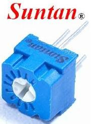
Suntan hot offer Trimming Potentiometer-3323

Suntan offer full kinds of Trimming Potentiometer as below. Please check http: / / http://www.suntan.com.hk/Trimming-Potentiometers/ for data sheet freely.

TSR-3006 - Rectangular Trimming Potentiometer
TSR-3323 - 4 Terminal Square Trimming Potentiometer
TSR-3296 - 5 Terminal Square Trimming Potentiometer
TSR-3362 - 7 Terminal Square Trimming Potentiometer
TSR-3386 - 8 Terminal Square Trimming Potentiometer
TSR-3329 - Circularity Trimming Potentiometer
TSR-3266 - 5 Terminal Square Trimming Potentiometer
TSR-3318 - 6mm Phenolic Round Trimming Potentiometer
TSR-3306 - 6mm Cermet Round Trimming Potentiometer
TSR-3309 - 9mm Round Trimming Potentiometer
TSR-065 - Phenolic Trimming Potentiometer
TSR-3590 - Precision Multiturn Wirewound Potentiometer
TSR-105H - 6 Terminal Trimming Potentiometer
Delivery: 2 weeks
Packing information: 50pcs/ tube
MOQ: 500 pcs

The Advantages of Ball Grid Array

A Ball Grid Array makes precise alignment and mounting possible. Before the Ball grid Array packaging, a single circuit board would sometimes require hundreds of pins. This presented a lot of positioning problems. When the assembly was heated, adjacent pins would sometimes get soldered together or form unplanned bridges.

One other advantage of Ball Grid Array packaging over other types of packaging involves heat conduction. A Ball Grid Array has less resistance to heat so heat flows readily from the mounted circuit components to the printed circuit board. This reduces the risk of overheating.

Finally, a Ball Grid Array assembly's contact points (point of contact between the surface solder balls and the printed circuit board itself is not readily apparent. This means greater data and application security.
Of course, a Ball Grid Array packaged integrated circuit is rather inflexible. Rigorous stress on the integrated circuit may cause the balls or the contact points to break off.

Manufacture of a Ball Grid Array Packaging

The manufacture begins with the basic circuit board, primed and printed. This printed circuit board for BGA has pads made of copper and these are arranged in the grid pattern that the solder balls are designed to have.

After the solder balls have been precisely arranged on the surface of the printed circuit board, the soldering process would begin. Surface mount soldering would proceed through reflow soldering (with the aid of a reflow oven that uses infrared or vapors as the heat source). At this point, the metal alloy balls would melt due to extreme temperatures. As the whole assembly cools, the solder balls will solidify and the package will become firmly affixed to the circuit board.

Ball Grid Array versus Pin Grid Array

There is one other common packaging for integrated circuits and this is the PGA or Pin Grid Array. The BGA looks physically similar to a Pin Grid Array package. Both are one-sided; that is, only one face of the semi-conducting substrate is used for printing and mounting of circuit components. Moreover, both have an obvious grid-like pattern. However, the Pin Grid Array uses pins - thus, the name - whereas the BGA uses balls - as it has already been mentioned above. The pins (in the PGA) or the balls (in the BGA) are the materials through which electricity is conducted between the printed surface of the semiconductor board and the surface-mounted circuit components.

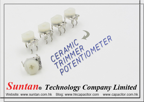
Suntan Ceramic Trimmer Potentiometer

Suntan Technology Company Limited
----All Kinds of Capacitors

Ceramic Trimmer Potentiometer Features

  1. 6mm Round/ Single-Turn/ Cermet Industrial/ Open Frame
  2. Cross slot adjustment options
  3. Horiontal andvertical mounting styles
  4. Dust resistant/ splash resistant covers
  5. PC board stand-offs and retention feature
  6. Front and top adjust styles

Ceramic Trimmer Potentiometer Electrical Characteristics

  1. Standard Resistance Range 100Ω to 1meg ohm
  2. Resistance Tolerance ±20% (TK±25%)
  3. Adjustment Angle 240°C ± 20°C
  4. Residual Resistance ≤500Ω, 10Ω>500Ω, 2% 

Ceramic Trimmer Potentiometer Pictures

Circularity Trimming Potentiometers

Circularity Trimming Potentiometers Features

  1. (Single Turn/ Cermet/ Industrial/ Sealed)
  2. (5 Terminal S tyles)

Circularity Trimming Potentiometers Electrical Characteristics

  • Standard Resistance Range 50Ω - 2MΩ
  • Resistance Tolerance ±5%, ±10%
  • Absolute Minimum Resistance ≤1% R or 2Ω
  • Contact Resistance Variation CRV≤3%or 3Ω
  • Insulation Resistance R1≥1GΩ(100Vac)
  • Withstand Voltage 500Vac
  • Effective Travel 280°

Circularity Trimming Potentiometers Pictures

Circularity Trimming Potentiometers

Round Trimming Potentiometers

Round Trimming Potentiometers Features

  1. (Single Turn/ Cermet/ Industrial)
  2. (2 Terminal S tyles)

Round Trimming Potentiometers Electrical Characteristics

  • Standard Resistance Range 10Ω - 2MΩ
  • Resistance Tolerance ±30% std
  • Absolute Minimum Resistance 1% max (≤2K=30Ω)
  • Contact Resistance Variation 3% max
  • Resistance Essentially infinite
  • Adjustment Angle 235° nom

Round Trimming Potentiometers Contact