Trimmer (electronics)

A trimmer is a miniature adjustable electrical component. It is meant to be set correctly when installed in some device, and never seen or adjusted by the device's user. Trimmers can be variable resistors (potentiometers) or variable capacitors. They are common in precision circuitry like A/V components, and may need to be adjusted when the equipment is serviced. Unlike other variable controls, trimmers are mounted directly on circuit boards, turned with a small screwdriver and rated for many fewer adjustments over their lifetime. In 1952, Marlan Bourns patented the world's first trimming potentiometer, trademarked "Trimpot".

Rectangular Trimming Potentiometers

Rectangular Trimming Potentiometers Features

  1. (Multiturn/ Cermet/ Industrial/ Sealed)
  2. (3 Terminal Styles)

Rectangular Trimming Potentiometers Parameters download PDF files Download TSR-3006 - Rectangular Trimming Potentiometers PDF

Rectangular Trimming Potentiometers Electrical Characteristics
Standard Resistance Range 10Ω - 5MΩ
Resistance Tolerance ±5%, ±10%
Absolute Minimum Resistance ≤1% R or 2Ω
Contact Resistance Variation CRV≤1%or 1Ω
Insulation Resistance R1≥1GΩ(100Vac)
Withstand Voltage 640Vac
Effective Travel 22 turns nom

Polypropylene Capacitors

This capacitor is used when a higher tolerance is necessary than polyester capacitors offer. Polypropylene film is used for the dielectric. It is said that there is almost no change of capacitance in these devices if they are used with frequencies of 100KHz or less.

The pictured capacitors have a tolerance of ±1%.

From the left in the photograph
Capacitance: 0.01 µF (printed with 103F)
[the width 7mm, the height 7mm, the thickness 3mm]
Capacitance: 0.022 µF (printed with 223F)
[the width 7mm, the height 10mm, the thickness 4mm]
Capacitance: 0.1 µF (printed with 104F)
[the width 9mm, the height 11mm, the thickness 5mm]

Polyester Film Capacitors

This capacitor uses thin polyester film as the dielectric.

They are not high tolerance, but they are cheap and handy. Their tolerance is about ±5% to ±10%.

From the left in the photograph
Capacitance: 0.001 µF (printed with 001K)
[the width 5 mm, the height 10 mm, the thickness 2 mm]
Capacitance: 0.1 µF (printed with 104K)
[the width 10 mm, the height 11 mm, the thickness 5mm]
Capacitance: 0.22 µF (printed with .22K)
[the width 13 mm, the height 18 mm, the thickness 7mm]

Electric Double Layer Capacitors (Super Capacitors)

  • This is a "Super Capacitor," which is quite a wonder.
  • The capacitance is 0.47 F (470,000 µF).
  • I have not used this capacitor in an actual circuit.

Care must be taken when using a capacitor with such a large capacitance in power supply circuits, etc. The rectifier in the circuit can be destroyed by a huge rush of current when the capacitor is empty. For a brief moment, the capacitor is more like a short circuit. A protection circuit needs to be set up.

The size is small in spite of capacitance. Physically, the diameter is 21 mm, the height is 11 mm.

Care is necessary, because these devices do have polarity.

Su Suntan Analyze How Capacitors Work

Suntan Technology Company Limited
---All kinds of Capacitors


In a way, a capacitor is a little like a battery. Although they work in completely different ways, capacitors and batteries both store electrical energy. If you have read How Batteries Work, then you know that a battery has two terminals. Inside the battery, chemical reactions produce electrons on one terminal and absorb electrons on the other terminal. A capacitor is much simpler than a battery, as it can't produce new electrons -- it only stores them.

In this article, we'll learn exactly what a capacitor is, what it does and how it's used in electronics. We'll also look at the history of the capacitor and how several people helped shape its progress.

Inside the capacitor, the terminals connect to two metal plates separated by a non-conducting substance, or dielectric. You can easily make a capacitor from two pieces of aluminum foil and a piece of paper. It won't be a particularly good capacitor in terms of its storage capacity, but it will work.

In theory, the dielectric can be any non-conductive substance. However, for practical applications, specific materials are used that best suit the capacitor's function. Mica, ceramic, cellulose, porcelain, Mylar, Teflon and even air are some of the non-conductive materials used. The dielectric dictates what kind of capacitor it is and for what it is best suited. Depending on the size and type of dielectric, some capacitors are better for high frequency uses, while some are better for high voltage applications. Capacitors can be manufactured to serve any purpose, from the smallest plastic capacitor in your calculator, to an ultra capacitor that can power a commuter bus. NASA uses glass capacitors to help wake up the space shuttle's circuitry and help deploy space probes. Here are some of the various types of capacitors and how they are used.

  • Air - Often used in radio tuning circuits
  • Mylar - Most commonly used for timer circuits like clocks, alarms and counters
  • Glass - Good for high voltage applications
  • Ceramic - Used for high frequency purposes like antennas, X-ray and MRI machines
  • Super capacitor - Powers electric and hybrid cars

In the next section, we'll take a closer look at exactly how capacitors work.

Su Suntan Electrochemical Type Capacitors

Suntan Technology Company Limited
---All kinds of Capacitors

Aluminum is used for the electrodes by using a thin oxidization membrane.

Large values of capacitance can be obtained in comparison with the size of the capacitor, because the dielectric used is very thin.

The most important characteristic of electrolytic capacitors is that they have polarity. They have a positive and a negative electrode.[Polarised] This means that it is very important which way round they are connected. If the capacitor is subjected to voltage exceeding its working voltage, or if it is connected with incorrect polarity, it may burst. It is extremely dangerous, because it can quite literally explode. Make absolutely no mistakes.

Generally, in the circuit diagram, the positive side is indicated by a "+" (plus) symbol.

Electrolytic capacitors range in value from about 1µF to thousands of µF. Mainly this type of capacitor is used as a ripple filter in a power supply circuit, or as a filter to bypass low frequency signals, etc. Because this type of capacitor is comparatively similar to the nature of a coil in construction, it isn't possible to use for high-frequency circuits. (It is said that the frequency characteristic is bad.)

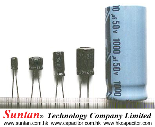
The photograph on the left is an example of the different values of electrolytic capacitors in which the capacitance and voltage differ.

From the left to right:

  • 1µF (50V) [diameter 5 mm, high 12 mm]
  • 47µF (16V) [diameter 6 mm, high 5 mm]
  • 100µF (25V) [diameter 5 mm, high 11 mm]
  • 220µF (25V) [diameter 8 mm, high 12 mm]
  • 1000µF (50V) [diameter 18 mm, high 40 mm]

The size of the capacitor sometimes depends on the manufacturer. So the sizes shown here on this page are just examples.

In the photograph to the right, the mark indicating the negative lead of the component can be seen. You need to pay attention to the polarity indication so as not to make a mistake when you assemble the circuit.

Su Suntan Capacitors

Suntan Technology Company Limited
---All kinds of Capacitors

  • The capacitor's function is to store electricity, or electrical energy.
  • The capacitor also functions as a filter, passing alternating current (AC), and blocking direct current (DC).
  • This symbol is used to indicate a capacitor in a circuit diagram.

The capacitor is constructed with two electrode plates facing eachother, but separated by an insulator.

When DC voltage is applied to the capacitor, an electric charge is stored on each electrode. While the capacitor is charging up, current flows. The current will stop flowing when the capacitor has fully charged.

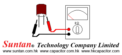
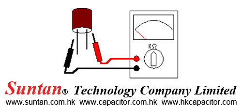
When a circuit tester, such as an analog meter set to measure resistance, is connected to a 10 microfarad (µF) electrolytic capacitor, a current will flow, but only for a moment. You can confirm that the meter's needle moves off of zero, but returns to zero right away.

When you connect the meter's probes to the capacitor in reverse, you will note that current once again flows for a moment. Once again, when the capacitor has fully charged, the current stops flowing. So the capacitor can be used as a filter that blocks DC current. (A "DC cut" filter.)

However, in the case of alternating current, the current will be allowed to pass. Alternating current is similar to repeatedly switching the test meter's probes back and forth on the capacitor. Current flows every time the probes are switched.

The value of a capacitor (the capacitance), is designated in units called the Farad ( F ).

The capacitance of a capacitor is generally very small, so units such as the microfarad ( 10-6F ), nanofarad ( 10-9F ), and picofarad (10-12F ) are used.

Recently, an new capacitor with very high capacitance has been developed. The Electric Double Layer capacitor has capacitance designated in Farad units. These are known as "Super Capacitors."

Sometimes, a three-digit code is used to indicate the value of a capacitor. There are two ways in which the capacitance can be written. One uses letters and numbers, the other uses only numbers. In either case, there are only three characters used. [10n] and [103] denote the same value of capacitance. The method used differs depending on the capacitor supplier. In the case that the value is displayed with the three-digit code, the 1st and 2nd digits from the left show the 1st figure and the 2nd figure, and the 3rd digit is a multiplier which determines how many zeros are to be added to the capacitance. Picofarad ( pF ) units are written this way.

For example, when the code is [103], it indicates 10 x 103, or 10,000pF = 10 nanofarad( nF ) = 0.01 microfarad( µF ).

If the code happened to be [224], it would be 22 x 104 = or 220,000pF = 220nF = 0.22µF.

Values under 100pF are displayed with 2 digits only. For example, 47 would be 47pF.

The capacitor has an insulator( the dielectric ) between 2 sheets of electrodes. Different kinds of capacitors use different materials for the dielectric.
Su Suntan Tantalum Bead Capacitors

Suntan Technology Company Limited
---All kinds of Capacitors

Tantalum bead capacitors are polarised and have low voltage ratings like electrolytic capacitors. They are expensive but very small, so they are used where a large capacitance is needed in a small size.

Modern tantalum bead capacitors are printed with their capacitance, voltage and polarity in full. However older ones use a colour-code system which has two stripes (for the two digits) and a spot of colour for the number of zeros to give the value in µF. The standard colour code is used, but for the spot, grey is used to mean × 0.01 and white means × 0.1 so that values of less than 10µF can be shown. A third colour stripe near the leads shows the voltage (yellow 6.3V, black 10V, green 16V, blue 20V, grey 25V, white 30V, pink 35V). The positive (+) lead is to the right when the spot is facing you: 'when the spot is in sight, the positive is to the right'. 

  • For example:   blue, grey, black spot   means 68µF
  • For example:   blue, grey, white spot   means 6.8µF
  • For example:   blue, grey, grey spot   means 0.68µF


Su Suntan Capacitance

Suntan Technology Company Limited
---All kinds of Capacitors

This is a measure of a capacitor's ability to store charge. A large capacitance means that more charge can be stored. Capacitance is measured in farads, symbol F. However 1F is very large, so prefixes are used to show the smaller values.

Three prefixes (multipliers) are used, µ (micro), n (nano) and p (pico):

  • µ means 10-6 (millionth), so 1000000µF = 1F
  • n means 10-9 (thousand-millionth), so 1000nF = 1µF
  • p means 10-12 (million-millionth), so 1000pF = 1nF

Capacitor values can be very difficult to find because there are many types of capacitor with different labelling systems!

There are many types of capacitor but they can be split into two groups, polarised and unpolarised. Each group has its own circuit symbol.